Saturday, 6 December 2014

Improvements and Fixing Issues

Improvements

The next step to upgrading from my Prototype, was to get the LED's to turn off after the key was released. Basically to understand note off signals. This has been a real struggle however and after hours of trying I still can't find a way to get the Arduino to register this. My idea seems ok enough and should work.

My idea is to use Max, to understand that when the note is released, it send a signal of 0 to the Arduino. In the code, the Arduino should register 0 and as a result of he 'else' function, all LEDs should turn off. However, getting Max to send a 0 has proved difficult. This is my next step and will continue working on it. Below is a screenshot of the Max patch in working progress, on the left is where I test the Max patch, and the right is where I build the tests before testing them.


Fixing Issues

A real issue I had with my Prototype was that one of the LEDs was always dimmer than the other two. I had a few theories to why this could be. First I thought it was the LED itself, but after switching LEDs around, it wasn't that. I always tried switching cables, resistors, even outputs from the Arduino. This became an issue I figured I would fix at a later date.

However, today I was reading back over my Arduino code, and I noticed something was missing. Below is the area I noticed the issue.

void setup() {
  // initialize serial communication:
  Serial.begin(9600);
  // initialize the LED pin as an output:
  pinMode(ledPin7, OUTPUT);
  pinMode(ledPin6, OUTPUT);
}

I realised that I never setup ledPin5 to be an Output! As a result, Arduino never considered the 3rd LED to be an Output signal, which meant a dim LED. All I had to do was change the code to this:

void setup() {
  // initialize serial communication:
  Serial.begin(9600);
  // initialize the LED pin as an output:
  pinMode(ledPin7, OUTPUT);
  pinMode(ledPin6, OUTPUT);
  pinMode(ledPin5, OUTPUT);
}

The Arduino now registers ledPin5 as an Output so now the LED receives the High voltage when triggered by the MIDI keyboard.

Thursday, 4 December 2014

Prototype

Here is the finished Prototype. This blog post is to present evidence of that. Below you will find:

  1. A video showing the Prototype functioning 
  2. A photo of the Prototype Arduino
  3. A copy of the Arduino code text
  4. A copy of the Max Patch code
  5. A Fritz diagram of the Arduino and breadboard layout
1. Video


2. Photo of prototype


3. Arduino Code


//Arduino Code, copy from here

const int ledPin7 = 7; // the pin that the LED is attached to
int ledPin6 = 6;
int ledPin5 = 5;


int incomingByte;      // a variable to read incoming serial data into

void setup() {
  // initialize serial communication:
  Serial.begin(9600);
  // initialize the LED pin as an output:
  pinMode(ledPin7, OUTPUT);
  pinMode(ledPin6, OUTPUT);
}

void loop() {
  // see if there's incoming serial data:
  if (Serial.available() > 0) {
    // read the oldest byte in the serial buffer:
    incomingByte = Serial.read();
    // if it's a 48 (Middle C), turn on the LED:
    if (incomingByte == 48) {
      digitalWrite(ledPin7, HIGH);
    } 
    // if it's anything else, turn off the LED:
    else {
      digitalWrite(ledPin7, LOW);
    }
    if (incomingByte == 50) {
      digitalWrite(ledPin6, HIGH);
    }
    else {
      digitalWrite(ledPin6, LOW);
    }
    if (incomingByte == 52) {
      digitalWrite(ledPin5, HIGH);
    }
    else {
      digitalWrite(ledPin5, LOW);
    }
  }
}

// to here

-----------------------------------------------------------------------------------------------------------------------

4. Max Patch

<pre><code>
----------begin_max5_patcher----------
681.3oc4WkraaCCD8rCP9GDzYWCtnM1a86nnHPxl0gA1TBTzotMn+6kKRVLI
PKznRtA8hnmgKZdu4wQie496VEVTdlVGF74fuFrZ0KJOqL9zdV05XU3w7yaO
jWaVXHm9ixhmBW2LmjdVZ7WSEr7CAaCHI.vko+dIWxyORMK4K5UbYJ9oikmj
GnRy4hZcWkK29Hiu+AAcqzFZXvFv5.TbrdHkXLTtB9V6dX6LmuJt9Dp6caOc
4Oqn1iIjwkgqCBC61nJFX71P.5Fz0reY1FDsAXb+66uSOpFVOYt5HstNeO88
jUVl+LDb.FhXXHHwvPwVirdXHXR+LTeTCZ4nlnz+tTC1GpI5eApo3jTVxudn
ZAIBL38DHpenVjy226kjkGVDefEXogUu0CkBVEuTRmiZgPfUNmNHYjMZoP8v
hoqUGeAULGzQh4IdXoQWckpbg58JohGn77hClH.LFUMn54CAWkFOYtJ9+ctB
hltvB+ghr5obktREi6OIhmv2izOiRFtt8jJUMbEqoRV1sGdfweWuuFPnm3MT
Xc4Iw11.pozZ.rKN1QqkLdtjo9.W2hzcZ4tpGY61Q4uRTbjsqpTgol.IMcSr
t+DKwo3uVKmWEqVKsLT2.x.uPBXTjD4KRvDSris8rCtXbqAB50qZx.AYzuNF
yKPFWaA7EHMZKaFgPVfLhQ0LZJAAttTBBi0CNFyHRPS9Vx0HtRgNhKswLhDv
jPRhuHg3hDxhfjo.jrqKiDE67kKmea+qH10P.yM5fSAcdUUNF2gnTza+MDXF
ZJTnMtwYuzqK6gcpUiSt4YoXeQgaVJKpUONun.MFJv9hhjDmaRHhevnoGs7p
pmoh5lHwh.U+rOUJz1Iqs1Lt011.Xnf9LqcKYVW4BUuoRUiomD1VZOmDEplw
7BUO9C.X.g4F
-----------end_max5_patcher-----------
</code></pre>

5. Fritz Diagram


Major Breakthrough in Prototype

Today I managed to finish my Prototype at least in fundamental form. I achieved this by learning how to get the Arduino to receive a signal from Max.

I achieved this by changing and adapting the PhysicalPixel example in the Arduino software. In the example, it was supposed to prove that you could recieve a signal from Max to control and LED. The example gives you the arduino code and a patch to copy and paste into Max. I actually found that this example didn't work for me, and no LED was triggered. However, I didn't give up. First here's the example arduino code with the Max Patch.

/*
  Physical Pixel

 An example of using the Arduino board to receive data from the
 computer.  In this case, the Arduino boards turns on an LED when
 it receives the character 'H', and turns off the LED when it
 receives the character 'L'.

 The data can be sent from the Arduino serial monitor, or another
 program like Processing (see code below), Flash (via a serial-net
 proxy), PD, or Max/MSP.

 The circuit:
 * LED connected from digital pin 13 to ground

 created 2006
 by David A. Mellis
 modified 30 Aug 2011
 by Tom Igoe and Scott Fitzgerald

 This example code is in the public domain.

 http://www.arduino.cc/en/Tutorial/PhysicalPixel
 */

const int ledPin = 13; // the pin that the LED is attached to
int incomingByte;      // a variable to read incoming serial data into

void setup() {
  // initialize serial communication:
  Serial.begin(9600);
  // initialize the LED pin as an output:
  pinMode(ledPin, OUTPUT);
}

void loop() {
  // see if there's incoming serial data:
  if (Serial.available() > 0) {
    // read the oldest byte in the serial buffer:
    incomingByte = Serial.read();
    // if it's a capital H (ASCII 72), turn on the LED:
    if (incomingByte == 'H') {
      digitalWrite(ledPin, HIGH);
    }
    // if it's an L (ASCII 76) turn off the LED:
    if (incomingByte == 'L') {
      digitalWrite(ledPin, LOW);
    }
  }
}

/*
Max/MSP version 5 patch to run with this example:

----------begin_max5_patcher----------
1672.3oc2ZszaaiCD9ryuBBebQVCQRYao8xhf1cQCPVfBzh8RRQ.sDsM2HSZ
HQmlzh9eu7gjsjsEk7y0oWjiHoHm4aluYHGlueUmtiDuPy5B9Cv8fNc99Uc5
XZR2Pm726zcF4knDRlYXciDylQ4xtWa6SReQZZ+iSeMiEQR.ej8BM4A9C7OO
kkAlSjQSAYTdbFfvA27o2c6sfO.Doqd6NfXgDHmRUCKkolg4hT06BfbQJGH3
5Qd2e8d.QJIQSow5tzebZ7BFW.FIHow8.2JAQpVIIYByxo9KIMkSjL9D0BRT
sbGHZJIkDoZOSMuQT.8YZ5qpgGI3locF4IpQRzq2nDF+odZMIJkRjpEF44M3
A9nWAum7LKFbSOv+PSRXYOvmIhYiYpg.8A2LOUOxPyH+TjPJA+MS9sIzTRRr
QP9rXF31IBZAHpVHkHrfaPRHLuUCzoj9GSoQRqIB52y6Z.tu8o4EX+fddfuj
+MrXiwPL5+9cXwrOVvkbxLpomazHbQO7EyX7DpzXYgkFdF6algCQpkX4XUlo
hA6oa7GWck9w0Gnmy6RXQOoQeCfWwlzsdnHLTq8n9PCHLv7Cxa6PAN3RCKjh
ISRVZ+sSl704Tqt0kocE9R8J+P+RJOZ4ysp6gN0vppBbOTEN8qp0YCq5bq47
PUwfA5e766z7NbGMuncw7VgNRSyQhbnPMGrDsGaFSvKM5NcWoIVdZn44.eOi
9DTRUT.7jDQzSTiF4UzXLc7tLGh4T9pwaFQkGUGIiOOkpBSJUwGsBd40krHQ
9XEvwq2V6eLIhV6GuzP7uzzXBmzsXPSRYwBtVLp7s5lKVv6UN2VW7xRtYDbx
7s7wRgHYDI8YVFaTBshkP49R3rYpH3RlUhTQmK5jMadJyF3cYaTNQMGSyhRE
IIUlJaOOukdhoOyhnekEKmZlqU3UkLrk7bpPrpztKBVUR1uorLddk6xIOqNt
lBOroRrNVFJGLrDxudpET4kzkstNp2lzuUHVMgk5TDZx9GWumnoQTbhXsEtF
tzCcM+z0QKXsngCUtTOEIN0SX2iHTTIIz968.Kf.uhfzUCUuAd3UKd.OKt.N
HTynxTQyjpQD9jlwEXeKQxfHCBahUge6RprSa2V4m3aYOMyaP6gah2Yf1zbD
jVwZVGFZHHxINFxpjr5CiTS9JiZn6e6nTlXQZTAFj6QCppQwzL0AxVtoi6WE
QXsANkEGWMEuwNvhmKTnat7A9RqLq6pXuEwY6xM5xRraoTiurj51J1vKLzFs
CvM7HI14Mpje6YRxHOSieTsJpvJORjxT1nERK6s7YTN7sr6rylNwf5zMiHI4
meZ4rTYt2PpVettZERbjJ6PjfqN2loPSrUcusH01CegsGEE5467rnCdqT1ES
QxtCvFq.cvGz+BaAHXKzRSfP+2Jf.KCvj5ZLJRAhwi+SWHvPyN3vXiaPn6JR
3eoA.0TkFhTvpsDMIrL20nAkCI4EoYfSHAuiPBdmJRyd.IynYYjIzMvjOTKf
3DLvnvRLDLpWeEOYXMfAZqfQ0.qsnlUdmA33t8CNJ7MZEb.u7fiZHLYzDkJp
R7CqEVLGN75U+1JXxFUY.xEEBcRCqhOEkz2bENEWnh4pbh0wY25EefbD6EmW
UA6Ip8wFLyuFXx+Wrp8m6iff1B86W7bqJO9+mx8er4E3.abCLrYdA16sBuHx
vKT6BlpIGQIhL55W7oicf3ayv3ixQCm4aQuY1HZUPQWY+cASx2WZ3f1fICuz
vj5R5ZbM1y8gXYN4dIXaYGq4NhQvS5MmcDADy+S.j8CQ78vk7Q7gtPDX3kFh
3NGaAsYBUAO.8N1U4WKycxbQdrWxJdXd10gNIO+hkUMmm.CZwknu7JbNUYUq
0sOsTsI1QudDtjw0t+xZ85wWZd80tMCiiMADNX4UzrcSeK23su87IANqmA7j
tiRzoXi2YRh67ldAk79gPmTe3YKuoY0qdEDV3X8xylCJMTN45JIakB7uY8XW
uVr3PO8wWwEoTW8lsfraX7ZqzZDDXCRqNkztHsGCYpIDDAOqxDpMVUMKcOrp
942acPvx2NPocMC1wQZ8glRn3myTykVaEUNLoEeJjVaAevA4EAZnsNgkeyO+
3rEZB7f0DTazDcQTNmdt8aACGi1QOWnMmd+.6YjMHH19OB5gKsMF877x8wsJ
hN97JSnSfLUXGUoj6ujWXd6Pk1SAC+Pkogm.tZ.1lX1qL.pe6PE11DPeMMZ2
.P0K+3peBt3NskC
-----------end_max5_patcher-----------
 */


For reasons I can't explain, it didn't work. However, it got me thinking back to my Prototype project which is about controlling 3 LED's with a MIDI keyboard. I figured "why not adapt this code to work in my favour?"

I started by connecting up 3 LED's to the Arduino using ports 5, 6, and 7. Then in the Arduino code, I changed the:

int ledPin = 13;

to:

int ledPin7 = 7;
int ledPin6 = 6;
int ledPin5 = 5;

This meant that I could use it integer to control each LED. I then chose which notes each LED would be assigned to, in this case I chose C, D, and E which is MIDI signal 48, 50, and 52 respectively.
All I needed to change in the code was that the incomingByte was going to 48 for ledPin7, 50 for ledPin6, and 52 for ledPin5. I also added an 'else' function for each one so that if the incomingByte was anything but it's corresponding MIDI number, it would recieve 0V, turning the LED off.

For Max, I used the Max patch I wrote earlier in another blog post (see blog post "Prototype Work" posted on the 01/12/2014). All I needed to change in the Max patch was that 'serial' object should be 'serial c 9600'. I used that object because it was an object we had used to control the Arduino in a previous University lecture.

Once I tidied up the code to be more presentable and added some comments of my own. I uploaded the code to the Arduino and ran the Max patch. It worked! I was now able to control 3 LED's using a MIDI keyboard. What was also good was that the LEDs turned off if another key was pressed that wasn't just the MIDI notes I wanted to use.

This is a major breakthrough in my development as I have not only achieved my first step in my proposal, but also the beginning of my second step. Below are photos of the Arduino and Breadboard, as well as screenshots of the Arduino code and Max Patch.


Arduino Code


Max Patch

Wednesday, 3 December 2014

Development of Prototype with Arduino

I had booked out an Arduino and made progress in understanding the Arduino and it's language.

I started by going through the learning section of the Arduino website. I went through every step of the Basics section. What this achieved, was a much greater understanding of using the Arduino and the code itself. I was also constantly referring to the Reference page as this had a key to explain terms such as:

setup () {
}

loop () {
}

Before going through this, the terms above meant nothing to me, I now understand that 'setup' is a function that organises code before running the 'loop' function which is basically the main program which loops. 


Once I began to understand the code a little more, I began asking questions to what I could change to actually make the Arduino do more than the example code. The first example that was successful was the DelayBlink example, which I got to blink multiple times at different times. Here's the code for that:


After achieving that, I began doing other things like getting it to light up connected LED's and changing which specific one to flash. For example, if I had an LED connected to port 6, I just changed the setep() to say:

void setup() {
   pinMode(6, OUTPUT);
{

This was an important to my development I believe as this broke the boundary between reading code to creating code and understanding what I was doing.

I did achieve other changes in code, unfortunately I did not save these changes or document them because of my excitement.

Links used for learning and research:

http://arduino.cc/en/Tutorial/HomePage

Monday, 1 December 2014

Prototype Work

I have been working towards my Prototype today. My Prototype product is a MIDI controller that can control at least 3 LED's with an Arduino. I will be gaining access to an Arduino soon, for now I am doing what I can without one. This includes doing research. A good source for code is the Learning section of the Arduino website, I will definitely be referring to that when I finally get my hands on an Arduino.

http://playground.arduino.cc/interfacing/MaxMSP


Other work is developing a patch with Max. It is patch that I hope will send numbers to the Arduino. I will be able to alter it when I get to use an Arduino. Currently all it can do is filter MIDI note information so that it triggers a message bang. I hope that this will be the fundamental to what will be needed to send note information to the Arduino to trigger an LED.


Saturday, 15 November 2014

Proposal

Proposal Project - MUS303 Interactive Sound Environments

Areas to be explored


This work will be exploring the ideas of data visualization, in particular with MIDI note information. The MIDI information is going to be received from an electric keyboard/piano. This may explore ideas around Toshio Iwai, with his “Piano - As Media Image” (Young, 2010). It will also look at performance based visualisation the same as Alva Noto and Ryuichi Sakamoto (Robin Chan, 2012).

Description of Project

For this project, I am proposing that I build an LED board that can be controlled with a Piano Keyboard. The basic principle will be that if I press a note on a keyboard, a specific corresponding LED will light up. It will also be possible to play multiple notes at once, which will light up simultaneous LED lights. As well as this, the lights will stay on for the length of sustain, this will include if a sustain pedal is used. It is unlikely that velocity will be taken into account at this point, but this may also be considered if the project leads that way.
What will this achieve?

When going to see live bands with keyboardists, they are often hidden behind keyboards, with little ability to express their skills with a visual indicator. This differs, for example, from a guitar player. A guitar player has his/her instrument facing the audience, and he/she can move about that stage freely to express the skills he/she possess. That being said, there is an instrument which can be used by keyboardists to reflect this very problem. A keytar. However, I found when watching live keytar players, that they are limited again to what they can do. Keytars are best played with one hand, which limits the skill of the player.

What the LED board will achieve, is a visual indicator of the skill and expression of the keyboardist. Not only that, audiences enjoy visual lighting during performances, and having lighting that is in time with the keyboardist can only increase the enjoyment of the show. Much the same way Alva Noto and Ryuichi Sakamoto do during their live performances.

So the aims of this project are:

  • To create a way that LED’s can be lit by playing a keyboard
  • The length of the LED should be controlled by length of note being played and/or through a sustain pedal
  • The LED’s should be presented in a way that would be visually pleasing to an audience.

Breakdown of how to fulfill this task

  1. The first task will be to get an LED to light up when triggered with a keyboard. This will be achieved with an Arduino and possibly MAX. This will break the boundary between getting a MIDI signal to activate the hardware and be the first major achievement.
  2. Second task will be to get a set of LED’s to light up to a corresponding note. This will be achieved by starting small, maybe one octave. Then move on to the full length of a keyboard, most likely 49 keys. This will require working out how to differentiate the MIDI signal to a corresponding LED.
  3. The next task will require getting multiple LED’s to light up when multiple notes are being played. The LED’s that light should be the correct corresponding LED. This will allow chords and full sequences to be played and light up the corresponding LED.
  4. The last task will be further improvements. Ideally, the length of the LED’s should be able to be controlled with a sustain pedal as well. Further improvements will also include presenting the LED’s in an appropriate way for an audience. This may be with multiple coloured LED’s and laying out the LED board in a way that it attaches to the back of a keyboard, on a stage, microphone stand, or possibly person. Having a way to hide any external components (Arduino, cables) will also be considered.

Issues that I may come across

The most probable Issue that I will have to overcome will be working with hardware. Getting a single LED to light up when a MIDI note is being played is a fairly straightforward task. However, getting the Arduino and/or MAX to understand multiple notes being played simultaneously and the sustain and the note off signals will be more difficult. I believe this will be my biggest challenge.

I may also find that getting the LED’s to sustain with a pedal will also be challenge. This is because the Arduino will have to deal with even more signals being sent to control the LED’s. Finding a way for the Arduino to understand and process all this information with little delay will probably be a massive issue.

Bibliography

Robin Chan. (2012) Alva Noto Ryuichi Sakamoto Live in 2012. [Online] Available from: https://www.youtube.com/watch?v=8ggEYoVKX_M [accessed 13 November 2014]

tcone. (2013) LED Piano Learning Strip. [Online] Available from: http://www.instructables.com/id/LED-Piano-Learning-Strip/ [accessed 13 November 2014]

Young, D. (2010) TOSHIO IWAI. [Online] Available from: http://www.inventinginteractive.com/2010/02/05/toshio-iwai/ [accessed 13 November 2014]

Change in Idea

I have decided to not focus on Binaural Microphones now. This is because I could not think of a good enough project to reflect the capabilities of Binaural Microphones well enough. I have now decided to focus on Data Visualization. Data Visualization is quite literally a visual representation of data. This can be any form of data visualization, from a map to a graph. In my case, I am going to focus data visualization for entertainment and music purposes. 
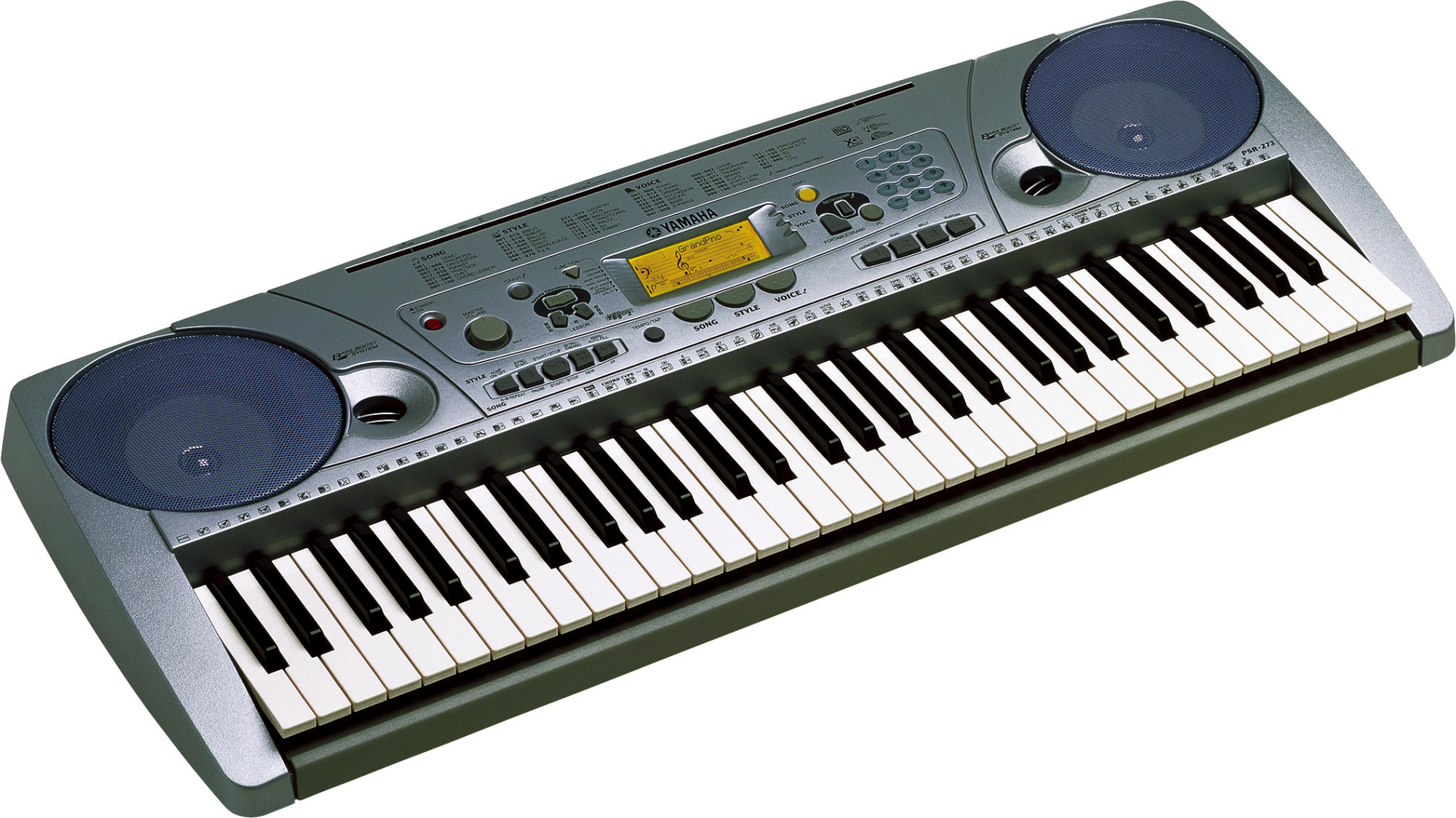
Yamaha PSR 273

My idea is to focus on using LEDs as a Data Visualization with a MIDI keyboard. I got this idea from the Yamaha PSR273 Keyboard that already has a similar feature. I actually used this keyboard to make a music video for Media Studies A2. The visual representation of lights, that was triggered when a note was played, was brilliant. See video below to understand what I am discussing.


This feature is great for visualization, and was even better for when learning a song. However, this type of visualizations only useful for the user of the keyboard. Their isn't one for a live music situation where the audience can see the visual. Not only that, it only registers the on/off signal, it doesn't take into account if a sustain pedal is being used.

Monday, 20 October 2014

Project Mindmap

As I am currently mind mapping ideas the link below goes to a mind-map website where you can view the mind-map that is still ongoing and in progress.

Link: http://goo.gl/KAHolh

Learning and Developing Max/MSP with Step Sequencer Project

In this module we are also learning to use Max/MSP. This is so we can use it to help with out projects. So far we have only covered the basics, but from learning Max/MSP, it has taken me two lectures to realise just how open Max can be. You can create so much. You are only limited by what you can think. To help develop my knowledge with Max, I set out on a task that I knew couldn't be too difficult, but was complicated enough to be a challenge. I decided to build a 16 step sequencer, as I figured out that it could be built using the majority of objects we had all ready learnt. 


Above is a screenshot of the finished step sequencer in patching mode. The purpose of the step sequencer is a sequencer that could be used with Kong Drum Designer in Reason 7.

The first task was to have a tempo that could be changed. This had not yet been covered in lectures, so through research and using the "help" in Max, I was able to learn how tempo was used.


The tempo has a default of 120 beats per minute with a beat multiplier of 1. The last part, beat divisions of a whole note, was confusing. However, eventually I figured the division could be used to divide the whole bar into 16 parts, which was helpful for the 16 step sequencer.


The next section used parts we had already learnt, such as: button, counter and % object. This allowed max to count up 16 bangs to a tempo and then loop back to 1, thus creating the 16 steps.


The select objects were used for two purposes. The first is the 0-15, which routed the bangs to 16 corresponding buttons steps. (see image below). This created not only a visual indicator, but also created the 16 bangs needed for the next section. The 0, 4, 8, 12 select object was used to create a click tempo but only clicking on the 4 beats of the bar. It works by being connected to a click object which is connected to an ezdac~ object. It's also routed though 4 buttons (shown below) for a visual indicator.   


After going through the buttons, the bangs are routed through ggate objects. Ggates had not been covered yet, however, their purpose was obvious from their visual interface and name. The ggates act as a switch to allow data through when opened by a trigger. After connecting all the bangs up to the ggates, each ggate was then connected to their own corresponding trigger. The triggers would become the interface the step sequencer would be controlled with.


Once the ggates have been triggered, the bang will be routed to a number message. There are 16 number messages ranging from 36 to 51. Each number message represents a MIDI note, 36 being C up to 51 being Eb. These MIDI notes were chosen as these are the MIDI notes used to control the Kong Drum Designer.

Finally the messages are routed to a makenote object and then to a noteout object. This sends the sequence out of Max to Reason.


Other features of the sequencer include: tempo control, on/off trigger (which can be triggered with the space bar), default button (which resets the tempo back to 120) and a reset button (which resets the whole sequencer.


When the sequencer is put in presentation mode, it is laid out in a very simple manner that is easy to use and simple in looks. 

This project took a total of 7 hours to complete, including research. Overall I am pleased with how the sequencer turned out. I'm most proud of how I didn't compare to other peoples sequencers as I knew this would make me aim to match other people's sequencers rather than create my own. It also meant that all thought processes were my own so the learning curve was much greater as it allowed me to learn from my own tests and failures rather than follow a tutorial.

A link to copy Max Patch Code:

Further development of the sequencer I would like to do:
  • Make it more visually pleasing by including a background, customizing switches etc.
  • Add more features such being able to change sounds within the sequencer, eq, compression etc.
  • Possibly the ability to add or remove sequences within the sequencer itself without changing the patching itself. So the user could have a customized 4x16 Step Sequencer or a 20x16 Step Sequencer. 
It is possible this could develop to be a final project but the primary purpose was not to be a final project, more of a practice.

Objects used in this project:

  • Key
  • Number
  • Select
  • Tempo
  • Button
  • Counter
  • %
  • Select
  • Ggate
  • Trigger
  • Message
  • Makenote
  • Noteout
  • Slider
  • Click~
  • Ezdac~
  • Comment


Introduction

This module requires me to create a prototype project, which will eventually lead to a final project, that reflects an idea based around something interactive in relation to sound. The first lecture discussed sound in a form of "sound space". This interests me in the idea that sound and music can be more than just a structural "song, composition, or film/T.V/game". It is still very broad however in what it is I can do. The second lecture covered a more specific idea of mobile creations or creations created using mobile technology. That included personal recorders and mobile apps. This interested me more as it also covered Binaural Microphones which I have an interest in.

I first came across Binaural Microphones when listening to a piece of audio that gave you the impression you were getting your hair cut called 'Virtual Barber Shop' (see link below). When remembering this I had a few ideas on how to create an interactive space that could simulate a similar experience like that. As this is my main idea I want to explore at the moment, my first task is to research further into Janet Cardiff, who explores the idea of using Binaural Microphones and interactive guides.

Link to Virtual Barber Shop: https://www.youtube.com/watch?v=IUDTlvagjJA